A synthetic node is a user-configured device in the Forward Networks model. A synthetic node represents a device or group of devices that Forward Networks cannot collect data from. Most often a synthetic node represents a private service provider network (such as a layer-3 VPN) or the public Internet itself.
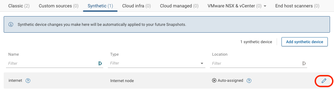
You can create or edit synthetic nodes under Sources > Synthetic. Note that there is always one Internet synthetic node.
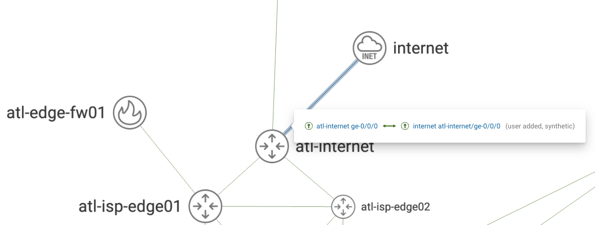
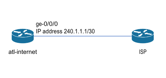
Suppose you have a connection from your network on a device called atl-internet on port ge-0/0/0, which connects to the service provider’s router. This interface has a public IP address, and you exchange BGP routes with the service provider over the link.
To add a link to the Internet synthetic node, click on the edit button under Sources > Synthetic > internet
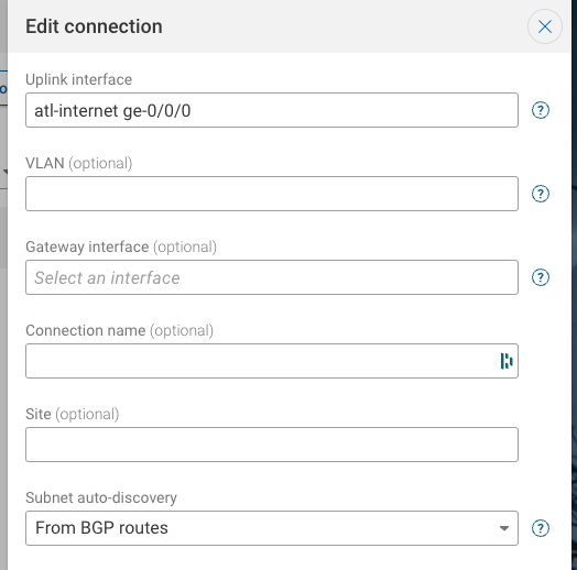
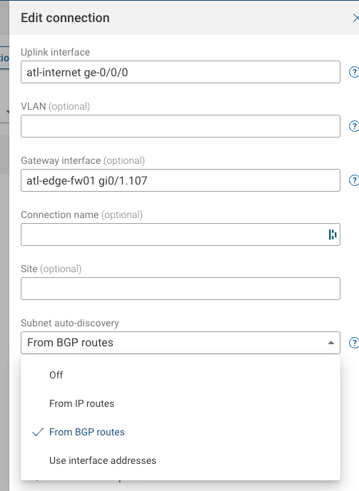
Under Uplink interface, type the name of the device and the physical interface (a list of available interfaces will appear after you type the device name, and you can select one).
Because you exchange BGP routes with the service provider on this link, choose From BGP routes for Subnet auto-discovery. ** Note that choosing this option will trigger the collection of BGP routes on the atl-internet device.
Another common scenario for Internet connectivity is having the physical connection to the service provider on a switch, but the actual layer-3 gateway on another device. In this scenario, it is necessary to specify the Gateway interface for the traffic. Consider the following network:
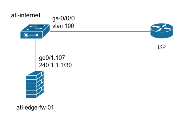
The physical interface that connects to the ISP is the same as before. However, this time the atl-internet device is behaving as a switch, and the public IP address is on ge0/1.107 on the atl-edge-fw-01 firewall.
The Gateway interface is the last layer-3 interface that Internet bound traffic traverses before leaving the network. It is also the interface on which BGP peering is performed with the ISP. (The traffic is simply trunked through VLAN 100 on the atl-internet switch).
The physical uplink in the synthetic node configuration is the same. But now you must enter atl-edge-fw01 gi0/1.107 as the Gateway interface.
Note that regardless of whether the Gateway interface is the same as the Uplink interface or not, that Forward Networks only shows the physical interface added to the topology. So both of the configurations above will yield the same physical topology diagram: